If a liquid-filled vessel is rotating, the liquid rises at the edges and forms a pit in the center. If the axis of rotation is exactly vertical, the shape of the pit is a paraboloid, whose radius of curvature is
( 1 ) R = (946 / ω) ², where ω = rotational speed.
In the formula, the quality of R is mm, if the rotational speed is in rpm. If, for example, ω = 33.3, becomes R = 806 mm, which would be suitable for an amateur telescope and easy to implement even with a turntable, for instance.
I started my own experiments a couple of years ago when I quickly realized that the most difficult part of the job was the precise erection of the axis of rotation. Turntables usually have a suspension designed to reduce the effects of vibration. However, such a structure is not suitable for rotating a liquid surface but must be made completely fixed and a separate tilting plane must be built under the player to erect the turntable. Below is a picture of my solution.
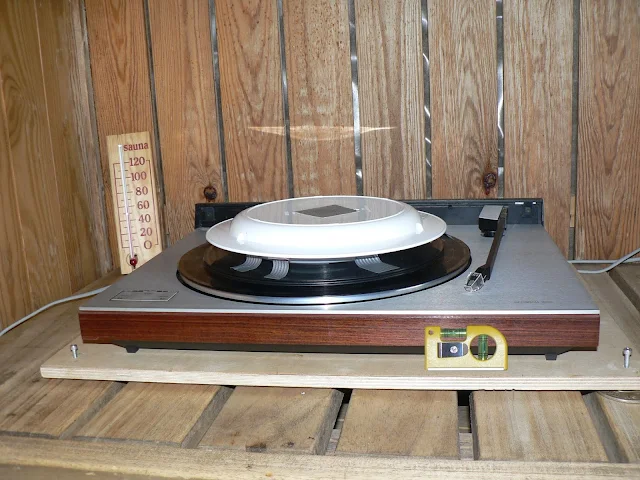 |
| Figure 1. Epoxy mold rotation mechanism. |
The hardware store spirit level shown in the picture was only suitable for rough installation of the player. The final erection was done with a precision level with a scale spacing of 10 ". Note the lowest stack of discs stacked on top of the player. Its purpose was to stabilize the flap seen on the disc shaft. Over the stack is the epoxy mold and a cover to prevent dust and bugs from falling.
The entire treatment was assembled on a wall-mounted sauna bench. This was because on the wooden floor the player tilted + -25" depending on where the operator was standing. This problem was not present in the sauna but there the stability of the benches became a problem. At the start of the casting. the erection error was always below +-1" but at the end, when the casting had dried, it typically was + -10 "in the depth and + -30" in the width direction.
Epoxy resin
The casting plastic, epoxy, was ordered from the net, where the suppliers can be found in the darkest of clouds. My choice fell on a company called LI HSI TECH CO., LTD because they had a good website and because they were also able to supply small test samples (1 kg). The choice was successful because the company's representative proved to be well acquainted with his field and willing to serve even small customers who may not know what they want. The range of epoxies available was large and customized for many different purposes. The differences between the substances are e.g. in their color, strength, viscosity and drying time.After a few pilot lot on the advice of the company representative, the products E-0001 and H-0001 (epoxy and hardener) were found good, They flow almost like water and dry surface dry in less than 20 hours.
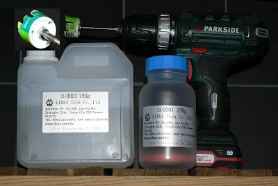 |
| Figure 2. LIHSI epoxy resin and the mixer. |
Mixing resin and hardener is then already its own art form, of which the web offers many good performances. Mine is that Mixing epoxy resin. With different substances, the mixing ratio varies but on my own, it was 1: 3. However, that relationship was not critical. If there was too much hardener, the mixture would only dry faster and vice versa. In my own experiments, the drying time was at most 2 days, when the mixture was a bit lean when the substance ran out. However, it eventually became hard too.
It is important for mirror making that the mixture retains the shape it has acquired during its initial rotation during drying. If the layer to be cast is strong, this will not succeed because during mixing the mixture heats up and then gradually cools as it dries. Through the heel, I learned that the first casting will never succeed. You have to cast first a casting base, on top of which you have to pour another thin layer. A suitable layer thickness appeared to be about 2 mm. It might work even thinner, but I didn't have time to try that when the substance ran out.
Test specimens
The first test piece was a lousy attempt, whose purpose was only to test the casting technique. The mold was a small plate, which was rotated at 45 rpm. Although the surface was visibly bad, it was Al-coated to see if that is possible and indeed, it succeeded well. The surface became very shiny, just like coated on glass,
Next, I tried to cast a small off-axis mirror - that is, one where the optical axis of the surface does not pass through the center of the mirror. However, this attempt failed because there was too little material and everything flowed to the outer edge of the mold, leaving the inner edge incomplete. I had calculated the epoxy demand assuming the axis of rotation was in the middle of the mirror!
Figure 3 below shows two other exemplars, which succeeded better and are still without coating.
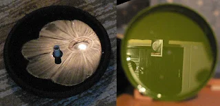 |
| Figure 3. Reflections from uncoated blanks |
The radius of curvature of the bottom was not measured, but on the second layer, it was R = 800 mm and on the third R = 781 mm. When the diameter of the box is 212 mm, the aperture ratio would be f / 1.8, which is a very respectable value. However, from figure 3 we can see that the reflection image is not good up to the edges, but must be cut at least 13 mm away from it. To be on the safe side, I limited it even more, leaving the final aperture ratio to f / 2.1
On a black plate (Fig. 3), the radius of curvature was R = 750 mm, corresponding ω= 34.5 rpm in equation 1. Later I sawed off its center pin, which was an error. When sawing, the surface became hot and the reflection image clearly deteriorated. The new value of the radius of curvature became R = 672 mm. A similar but minor defect also occurred on the surface of the green box when I drilled 4 holes in the bottom for gluing the mounting screws.
Mirror testing
The easiest way to test a telescope mirror at home is to look at the image of the point light source it forms in different positions of focus. With a flawless mirror, the image is sharp in focus and a round plate evenly illuminated in extra or infrared. If a bright dot appears in the center of the plate in one position and a rounder ring in the other, either an over- or under-corrected spherical aberration is defective. However, if there are rings visible, the mirror is not hopelessly bad but is at least suitable for burning glass.Below are the focus images of the mirrors in Figure 3. The light source was a small hole punched in aluminum foil which was reflected on white cardboard next to the light source and photographed there.
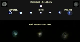 |
| Figure 4. Focusing images of good and bad mirrors. |
Experiment Telescope
The next step in testing was to use it in the right shooting situations. When there was no ready-made telescope for that purpose, one had to be quickly assembled. The end result is in the pictures below.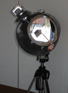 |
| Figure 5. |
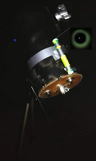 |
| Figure 6. |
The camera's optics can also be zoomed moderately, the only difficulty being that camera's automation tends to focus on the wrong subject and does not work in the dark at all.
Below is a photo, taken through three window panes, the accuracy of which, even with defects, is surprisingly good and clearly exceeds the expectations set at the beginning. By avoiding the slips described above, the result would undoubtedly be even better. Hopefully, some of the readers will take the challenge and makes a better one.
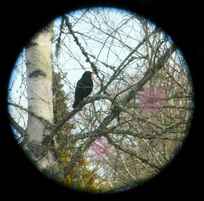 |
| Figure 7. Blackbird in a yard tree. In marked areas image resolution is poor. |
Photos, more in Finnish

Links:


Löysin netistä halvan vatupassimyyjän, alla linkki vastaisen varalle.
VastaaPoistahttps://www.aliexpress.com/item/32880883513.html